Carbon Steel Ultrasonic Testing: UT Levels and Standards
Ultrasonic testing (UT) is the go-to volumetric inspection for carbon steel plate, pipe and forgings — it finds the laminations, inclusions and internal cracks that no visual check or dimensional report can catch. Yet UT is also one of the most under-specified requirements in purchase orders: buyers write “UT tested” and leave the acceptance class undefined, which gives the mill no target and gives you no recourse. This guide explains the main UT standards, what the class and level designations actually mean, and how to write UT into a PO so the test is enforceable.
What UT Detects in Carbon Steel
A straight-beam probe sends a high-frequency pulse (typically 2–4 MHz) through the material and listens for echoes. A clean plate returns a clear backwall echo; a lamination, mid-wall inclusion or hydrogen crack reflects energy early, showing up as an indication between the initial pulse and the backwall. In plate and strip the dominant defects are rolling laminations and centerline segregation. In seamless pipe it is wall inclusions and laps; in ERW/HFW pipe it is weld-line fusion defects, which is why API 5L mandates angle-beam UT of the weld seam. In forgings it is inclusions, bursts and, in heat-treated parts, quench cracks.
The Three Standards That Matter Most
EN 10160 — flat plates ≥ 6 mm
EN 10160 defines two parallel classification systems: L-levels for laminations detected by straight beam (L1 to L4) and S-levels for smaller imperfection areas found by scanning pattern (S1 to S4, plus E-classes for edge inspection). Structural work commonly orders L2/S2, pressure-vessel plate L2/S3 or stricter. The higher the class, the finer the scanning grid and the smaller the permissible indication area.
ASTM A435 / A578 — plates
ASTM A435/A435M is the basic straight-beam test for heavy plate ≥ ½ in. (12.7 mm): acceptance requires no discontinuity that completely absorbs the backwall reflection, plus a defined registration level. ASTM A578/A578M adds straight-beam acceptance Levels A, B and C with discrete indication limits and optional angle-beam examination of zones. Level B (common for pressure parts) limits individual indications to 25 mm (1 in.) and total indications per defined area. These levels are what a mill means when a PO says “UT to A578 Level B”.
ISO 10893 / API 5L — welded and seamless pipe
ISO 10893 (parts 10–12) covers automated UT of seamless and welded tubes, while API 5L Annex E requires UT of the weld seam and defines acceptance levels PSL1/PSL2 with notch-based calibration. If you buy line pipe, API 5L already embeds the UT requirement — your job is to verify it appears on the certificate with the correct level.
| Product | Standard | Typical PO call-out |
|---|---|---|
| Structural plate ≥ 6 mm | EN 10160 | UT L2 / S2, report per heat and plate |
| Pressure vessel plate | EN 10160 or A578 | UT L2/S3 or A578 Level B |
| Heavy plate ≥ 12.7 mm (US) | ASTM A435 | UT per A435, straight beam |
| Seamless pipe | ISO 10893-10 | UT acceptance level L2 (or API 5L PSL2) |
| Forgings | ASTM A388 | UT per A388, 2.25 MHz straight + 45° angle |
How a Real UT Procedure Runs
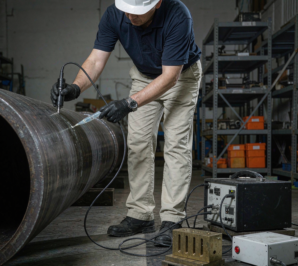
A compliant UT sequence is: (1) surface preparation to Sa 2.5 or smooth scale-free condition, since loose scale kills coupling; (2) calibration on a reference block of the same thickness — notches or flat-bottom holes per the standard; (3) system check of gain, transfer correction and screen range; (4) scanning on a defined grid (EN 10160 uses 100 mm nominal lines with 10 % overlap minimum) at a controlled speed; (5) recording of indications above the registration level with location sketches; (6) signed report referencing heat numbers and plate identities.
For angle-beam work (seam welds, forgings) the probe angle is typically 45° or 60°, calibrated on a side-drilled hole, with the distance-gain-size (DGS) or DAC curve recorded. Operators must hold ISO 9712 or ASNT SNT-TC-1A Level II certification — ask for the operator certificates together with the UT report, because an unqualified operator is the most common reason UT results do not survive a dispute.
Acceptance Criteria in Numbers
Buyers should understand what the classes translate to physically. Representative limits:
- EN 10160 L2: no single imperfection area larger than 100 cm², and total imperfections bounded per square metre of plate — a practical “no gross lamination” level.
- EN 10160 S2: scanning lines at 100 mm pitch; acceptable imperfection sizes and frequency limited per the standard’s tables.
- ASTM A578 Level B: individual straight-beam indications must not exceed 25 mm in length, and grouped indications are summed and limited per plate area.
- ASTM A435: any discontinuity producing complete loss of backwall is rejectable; indications above the registration level must be evaluated.
One subtlety worth stating in the PO: for thick plates, thin near-surface laminations fall in the “dead zone” of a standard straight-beam probe. If your application (e.g. machining a flange face or cutting tube sheets) exposes mid-thickness surfaces, specify near-surface scanning or a dual-crystal probe requirement.
When Should a Buyer Require UT?
As a rule of thumb: require UT on plate thicker than 25 mm for structural work, on all pressure-vessel plate, on tube sheets and blocks that will be drilled deep, on machined forgings, and on any plate destined for heavy welding where a lamination would propagate under load. For standard thin sections where UT is not standard practice, insisting on it adds cost without much risk reduction — mill surface inspection plus a tensile/impact program covers most of the risk there.
Writing UT Into Your Purchase Order
- Name the standard and class: “UT per EN 10160, class L2/S2” — not just “UT tested”.
- Define reporting: per-plate UT report with heat number, instrument, probe, calibration block reference and operator level.
- State witness requirements: if a third party (SGS, BV, TUV) must witness UT, say so — mills need lead time to schedule.
- Specify post-cutting re-checks: after flame cutting or machining, edges can reveal what the original scan grid missed; decide upfront whether re-inspection of cut edges is included.
- Reject and replacement path: state that rejected plates are replaced or refunded with freight, so the claim is mechanical, not a negotiation.
Common Findings and What Happens Next
The most frequent finding on plate is a lamination — a planar, mid-thickness separation usually caused by ingot or slab porosity that did not fully weld shut during rolling. Small isolated laminations away from weld lines may be acceptable under some codes after engineering review; larger or edge-adjacent ones require cropping or rejection. On pipe, seam indications are usually ground, re-welded and re-tested only where the product standard permits repair; otherwise the joint is cut out. In forgings, indications near a machined surface can often be removed with extra machining allowance — which is why telling the mill the final machined dimensions before UT saves material.
A Case Example: Lamination Found Before Fabrication
A recent tube-sheet order illustrates why UT class matters. The buyer ordered 60 mm A516-70 plates for drilling into tube sheets and specified UT to EN 10160 L2/S2 after we recommended it — the initial quote had assumed surface inspection only. During mill UT, one plate of five showed a 90 cm² lamination in the mid-thickness, well clear of the plate edge. Because the class was written in the PO, the mill cropped the affected zone and re-rolled a replacement plate without a claim cycle: the acceptance rule was pre-agreed, so disposition took days, not weeks. Had the plate been drilled first, the lamination would have surfaced as a through-hole anomaly during drilling — eight drilled holes’ worth of scrap and a production delay. The lesson generalizes: UT is cheapest when it is ordered with the plate and verified at the mill, and most expensive when it is discovered by your own fabrication line.
FAQ
What is the difference between UT Level B and Level C in ASTM A578?
Level B is the standard quality level for general pressure-part plate, limiting individual indications to 25 mm with grouped-indication limits. Level C is stricter — smaller permissible indications and closer scan pitch — used for high-integrity parts such as nuclear or critical vessel shells. Choose B unless your design code forces C.
Does UT replace X-ray testing?
No. UT is best for planar defects in plate, forgings and welds; radiography (RT) images volumetric defects like porosity and slag in welds. For welded pipe, API 5L uses UT on the seam; for pressure vessel welds, codes choose UT or RT per joint type. They are complementary, not interchangeable.
How much does UT add to plate cost and lead time?
Mill-performed UT to L2/S2 typically adds 2–5 % to plate price and, if not a stock item, 2–5 days. Third-party witnessing adds a few hundred USD per visit. Compared with fabricating on laminated plate, it is the cheapest quality gate you can buy.
Can UT detect defects in galvanized or painted steel?
UT works through coatings — coupling gel transfers sound even across paint or galvanizing — but heavy rust or loose scale must be removed. For in-service structural inspection, UT over intact coating is standard practice.
What certificate should I expect for UT?
Either a dedicated UT report (with scan sketches and equipment details) or a line on the EN 10204 3.1 MTC stating the standard, class and result. A bare MTC statement “UT ok” without a class reference is not verifiable and should be challenged.
Source UT-Tested Carbon Steel With Enforceable Reports
Huaxia-Steel supplies plate, pipe and forgings with UT to EN 10160 L2/S2, ASTM A578 Level B or API 5L PSL2 as specified, with third-party witness arrangements on request. Send us your specification and we will quote with the UT class written into the offer.