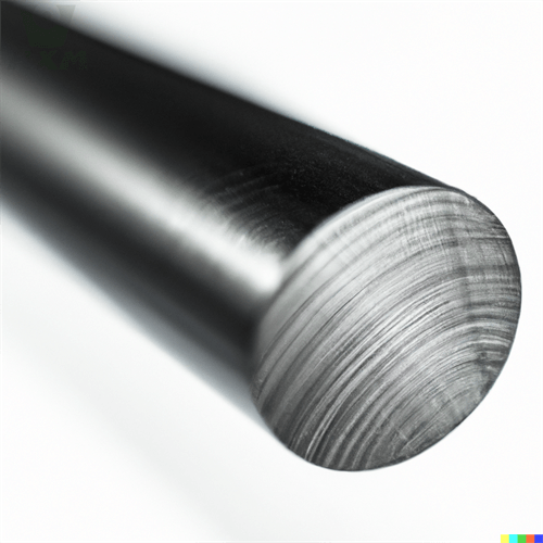
Carbon steel fin tube — most commonly helical solid fin tube (HFW, high-frequency welded) — is the heat-transfer element that makes modern boilers, economizers, air preheaters, waste-heat recovery units and air coolers compact and efficient. A base tube carries fluid while an externally attached continuous helical fin multiplies the outside surface area by 8-20 times, moving the thermal bottleneck from the gas side to the tube side. We supply solid and serrated fin tubes in carbon steel base tube with carbon steel or stainless fins, wound on our own finning lines and delivered bare, painted, or assembled into tube bundles.
Product Overview
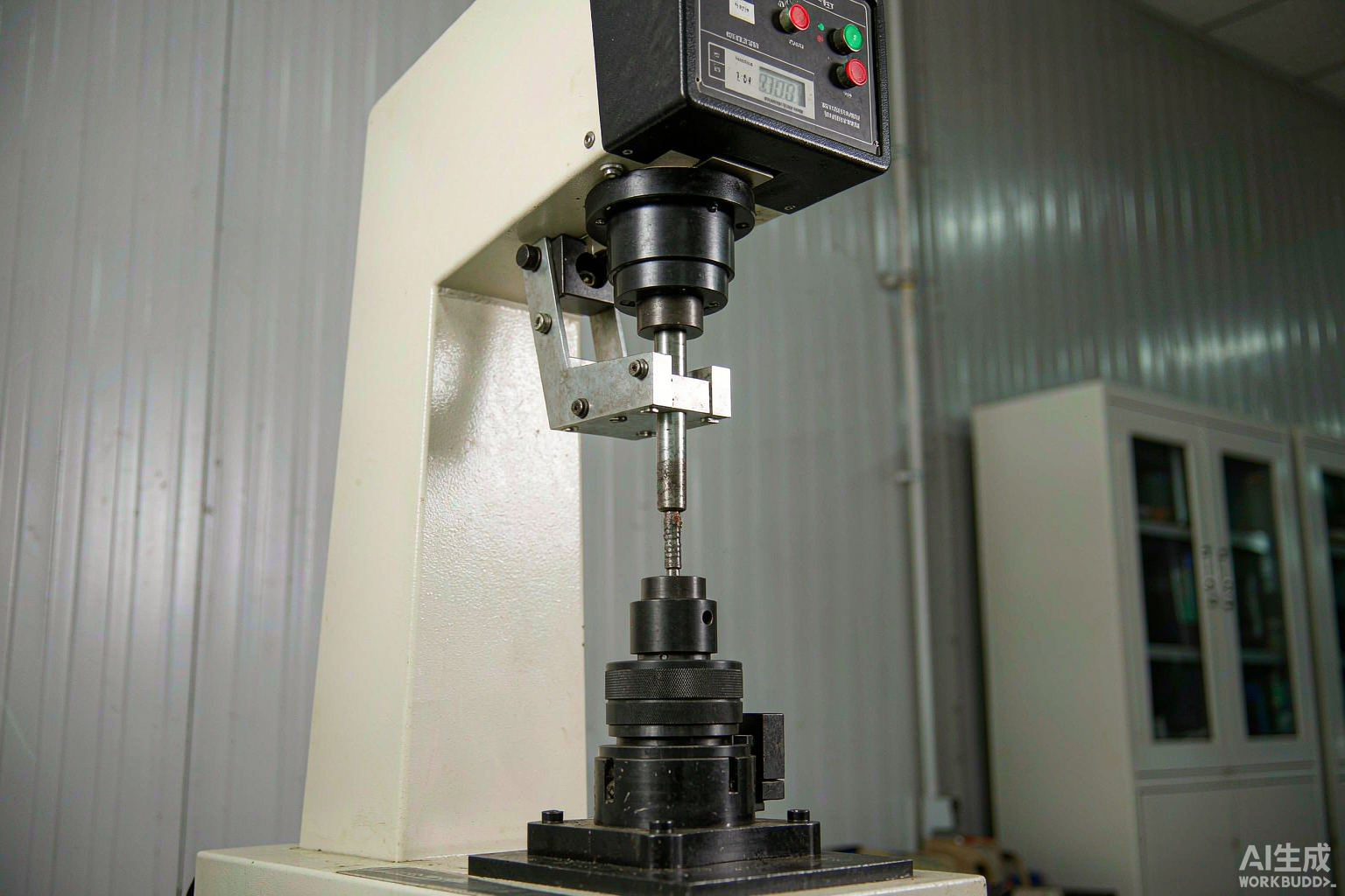
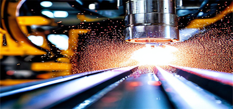
In an HFW (high-frequency welded) fin tube, a steel strip is continuously wound helically onto the base tube and welded to it by resistance heating at the contact point — the weld takes place under pressure at roughly 400-500 kHz, producing a bond with a weld-to-base-metal ratio typically above 80% and thermal contact resistance negligible in service. Alternative attachment methods we support include L-footed/embedded (L/LL/KL/G) tension-wound aluminum or steel fins for lower-temperature service, and extrusion for bimetal configurations.
Serrated (segmented) fins — cut into small teeth around the helix — increase the heat-transfer coefficient by 15-25% in turbulent gas streams by repeatedly breaking the boundary layer, at the cost of a small pressure-drop increase. The correct fin geometry decision depends on gas velocity, fouling tendency and allowable draft loss; we help customers select before quoting.
Specifications, Dimensions and Weight
| Item | Range / Value |
|---|---|
| Base tube OD | 16 mm – 219 mm (common: 25.4 / 31.8 / 38 / 44.5 / 50.8 / 63.5 / 76 / 89 / 114 mm) |
| Base tube wall | 1.5 mm – 12 mm (per ASTM A179 / A192 / A106 / A214 / GB 3087 / GB 5310) |
| Fin height | 6 mm – 30 mm (typical 12–19 mm) |
| Fin thickness | 0.8 mm – 3.0 mm (common 1.2 / 1.5 / 2.0 mm) |
| Fin pitch | 2.0 mm – 12.7 mm (2–8 fins per inch typical) |
| Fin type | Solid (plain) helical, serrated (segmented), studded; L/LL/KL/G embedded |
| Tube length | Up to 18 m (single piece); longer by orbital welding |
| Surface area ratio | 8 – 20 × bare tube external area, depending on fin height and pitch |
| Bare ends | 50–150 mm each end (for tube sheet expansion/welding), or per drawing |
| Weld bond ratio | ≥ 80% typical, verified by destructive peel test |
| Weight gain vs bare tube | Typically +40% to +120% depending on fin geometry (see table below) |
Weight example: a 50.8 mm OD × 3.6 mm wall base tube weighs 4.19 kg/m bare; with 19 mm high, 1.5 mm thick fins at 6 mm pitch (approx. 4.2 fins per inch) the finished fin tube weighs about 8.6 kg/m and provides roughly 1.2 m² of external surface per meter of tube length — against 0.16 m² for the bare tube, a 7.5× gain. Estimate your bundle weight this way before sizing lifting equipment.
Fin Geometry and Performance Reference
| Fin pitch (mm) | Fin height (mm) | Fin thickness (mm) | Ratio (fin/bare area) | Weight gain |
|---|---|---|---|---|
| 4.2 | 12 | 1.2 | ~7.0 | +55% |
| 6.0 | 15 | 1.5 | ~6.0 | +60% |
| 8.0 | 19 | 2.0 | ~5.5 | +80% |
| 12.7 | 25 | 2.5 | ~4.5 | +95% |
Available Grades
- Base tube: ASTM A179 (seamless cold drawn low-carbon), A192 (boiler), A106 Gr B (high temp seamless), A214 (ERW carbon steel heat exchanger tube), A210, GB 3087 / GB 5310, DIN 17175 St35.8 / St45.8, JIS STB340 / STB410.
- Fin material: carbon steel strip (SPCC, Q195/Q235, ASTM A109), weathering steel, or stainless steel (304/316/409/410) for corrosive flue gas.
- Bimetal option: carbon steel base with stainless or alloy fin where the tube side is clean and the gas side is corrosive — commonly the most economical compromise.
- Related products: studded tube, H/HH fin tube (double tube, square fins), finned U-bends, hairpin assemblies, and complete economizer or air preheater tube bundles with headers.
Manufacturing and Inspection Standards
Fin tube production follows the base tube standard plus finning acceptance criteria agreed with the customer. Typical reference documents: ASTM A1012 for welded carbon steel fin tube general requirements, TEMA (Tubular Exchanger Manufacturers Association) classes R/C/B for exchanger bundles, ASME Section II for material, and ISO 9001 process control. Inspection items:
| Test | Method / acceptance |
|---|---|
| Base tube hydrostatic test | Per base tube standard (e.g. A179 at 1.5 × design pressure) before finning |
| Fin weld bond | Destructive peel/bend test on sample per batch; bond ratio ≥ 80% |
| Fin pitch and height | Gauge measurement, ±0.3 mm pitch typical |
| Dimensional runout | Fin concentricity and straightness check per length |
| Finned tube hydro / pneumatic | Per order; typical 1.5 × design pressure, 10–30 s hold |
| Surface and coating | Visual; optional hot-dip galvanizing (80–120 µm), aluminizing, or paint |
| Documentation | Base tube MTC (EN 10204 3.1), finning process record, dimensional report |
Applications
Carbon steel fin tube is installed in: boiler economizers and superheater support zones, waste heat recovery units (WHRU) behind gas turbines and engines, air preheaters, air-cooled heat exchangers and fin-fan coolers, process gas coolers, ammonia and urea plant exchangers, HVAC and drying systems, and heat recovery steam generators. Selection logic runs on three constraints: gas-side temperature (carbon steel fins are generally limited to about 450-480 °C in continuous service, above which oxidation accelerates), gas-side corrosion and dew point (sulfur-bearing flue gas below the acid dew point needs stainless or enamel protection), and fouling tendency (dusty gas calls for wider pitch, serrated fins help less than the sales brochure suggests when fouling dominates).
Design and Ordering Guidance
Before requesting a quotation, define: base tube OD and wall, material and standard; fin material, height, thickness, pitch and type (solid or serrated); finished tube length and bare-end length; quantity in meters or pieces; end preparation (bevel, plain, U-bend radius); and any testing requirements beyond standard. If you are replacing an existing bundle, a photograph of the tube end and a fin-pitch gauge measurement are usually enough to identify the geometry — we keep tooling for the common DIN/Imperial pitch combinations and can match legacy bundles without new tooling cost. For new designs, our engineers can run a thermal comparison between two or three fin geometries so the choice is made on duty, not habit.
Quality Assurance
Finned tubes are produced under ISO 9001 with process monitoring of welding power, tension and pitch on every tube; samples are destructively tested each shift to confirm bond quality. Base tubes arrive with heat-specific MTCs, and finished tubes carry traceability to the base tube heat. Optional: 100% hydrostatic testing of finned tubes, eddy current or ultrasonic testing of the base tube, PMI verification of fin material, coating thickness verification for galvanized product, and third-party inspection (SGS, BV, TUV, Intertek, DNV) including witnessed peel tests and dimensional survey. For critical boiler service we can supply full material traceability packages aligned with ASME documentation requirements.
Packaging and Shipping
Finished fin tubes are bundled in hexagonal or square packs with timber spacers between layers to protect fins, strapped with flat steel banding over edge protectors, and wrapped in woven cloth or shrink film. Bundles are packed in steel-framed crates or open-top containers for long lengths; tube ends are capped. For galvanized or painted tubes, separators prevent coating damage in transit. Each bundle is tagged with item number, size, fin specification, quantity and length. Typical lead time: 15-25 days for standard geometry from stock base tube, 25-40 days for large or custom-tooled orders. MOQ: 500 meters per specification, negotiable for sample and replacement orders.
Comparison: Solid vs Serrated vs Studded
| Type | Heat transfer | Pressure drop | Fouling resistance | Typical service |
|---|---|---|---|---|
| Solid helical fin | Baseline | Lowest | Best — easy soot blowing | Clean gas, economizers, air coolers |
| Serrated (segmented) | +15–25% | +10–20% | Moderate — traps deposits | Clean gas where compactness matters |
| Studded | +5–10% | Moderate | Very good, robust | Dirty flue gas, refinery heaters |
| H/HH (square, twin tube) | Good | Low | Good — flat gas path | Waste heat boilers, incineration |
| L/LL/KL/G embedded | Good at low temp | Low | Fair | Air coolers below 200 °C |
The counter-intuitive result in the table is worth emphasising: serrated fins raise the heat transfer coefficient, but in fouling service the teeth collect deposits and performance falls below solid fin within weeks of operation. Choose serration for clean gas streams (natural gas fired units, clean air), and solid or studded for coal, biomass, refuse or cement kiln exhaust.
Why Source Fin Tube from Us
We operate finning lines alongside our tube mill, which means base tube and finning are scheduled as one production order rather than two — the practical difference is shorter lead time (typically 10-15 days faster than buying tube from one supplier and finning at another) and a single point of accountability when a question arises. We stock common base tube sizes in A179, A192 and A214 so replacement orders and urgent bundle repairs can ship quickly. Replacement bundles are our specialty: send end photographs and pitch measurements, and we reverse-engineer legacy geometry including obsolete Imperial pitches. Every order ships with base tube MTCs, a finning process record, and dimensional reports; third-party inspection is available at any stage.
Pricing and Lead Time Notes
Fin tube pricing is quoted per meter and driven by three variables: base tube weight (following the tube standard and wall thickness), fin strip weight (fin height × thickness × pitch — the dominant variable, since high dense fins can more than double material content), and processing cost (serrated fins run 10-15% above solid at equal geometry). Stainless fins add 30-80% over carbon steel fins depending on grade. Galvanizing adds USD 0.8-1.5 per meter at common sizes. Lead times: 15-25 days standard geometry from stock base tube, 25-40 days for custom or large orders, plus transit. MOQ 500 meters per specification, with trial and replacement orders negotiable — we regularly ship 50-200 meter replacement lots for bundle repairs because we understand that a failed economizer bundle idles an entire plant.
Send us your base tube size, fin height, pitch, material and quantity for a firm fin tube quotation within 24 hours — factory direct, with MTC, dimensional reports and third-party inspection available before shipment.